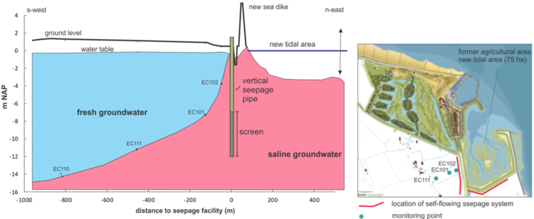
Below the adjacent agricultural area, a freshwater lens of about 10 to 15 meters provides farmers with fresh groundwater for irrigating their crops (figure 1). In order to protect this freshwater lens from shrinking, a self-flowing seepage system, called SeepCat, was designed and installed to compensate the effects resulting from this local sea level rise.
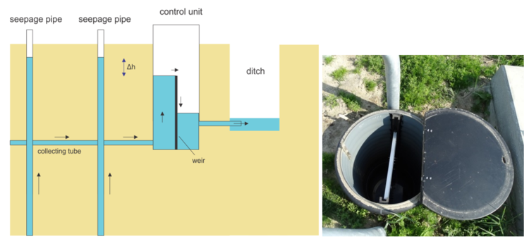
The freshwater lens below the agricultural area is one of the Badon Ghyben Herzberg type and will eventually shrink when hydraulic heads below the lens increase caused by the local sea level rise. The task of SeepCat is to release the increased pressure in the aquifer preventing the freshwater lens to decrease in size. The self-flowing seepage system consists of 61 vertical seepage wells with 5-10 m long screens, installed in the aquifer at 12 to 17 m depth. The distance between the wells is 15 to 20 m and the total length of the seepage system is 1100 m. The vertical seepage wells are connected in the subsoil with horizontal tubes which end up in control units (figure 2). The hydraulic head gradient (Δh) can be regulated by raising or lowering the water level in the control unit using weirs (figure 2). In this way the discharge of the seepage system can be regulated. Since the hydraulic head in the aquifer is higher than the surface water level in the control unit and ditch, seepage wells are artesian and self-flowing and no pumps are needed to extract the groundwater from the aquifer. The extracted seepage water is discharged into the surface water system and transported to a pumping station (at 1 km) where it is pumped out of the polder into the sea.

- Perkpolder tidal restauration, one year after realisation, draft progress report, Boersema, M., J. van der werf, P. de Louw, T. Ysebaert, T. Bouma, Centre of expertise Delta Technology, 27 november 2016.
Zie ook
- Perkpolder tidal restauration, one year after realisation, draft progress report
- Rammegors tidal restauration, final report
- Perkpolder Tidal Restauration
- Building with Nature; from concepts to practice
- Wadden Sea Plan 2010
- Is there a green solution for a blue-green problem leading to clear blue water?
- Civil Design of a Tidal Power Plant Case Brouwersdam
- A flood disaster in retrospect. Examing evacuation strategies by comparing the 1953 Dutch flood scenario with the present day situation
- Aspects of sediment- and morphodynamics of subtidal deposits of the Oosterschelde (the Netherlands)
- Identification and analysis of most vulnerable infrastructure in respect to floods


